
Artem Komarov explained that in sheet metal stamping, draw beads are the key elements controlling the sheet metal inflow for forming of large panels. Most studies focus on a single-bead design, which is limited in how much restraining force it can provide; only a few studies have covered multiple draw beads or other geometries.
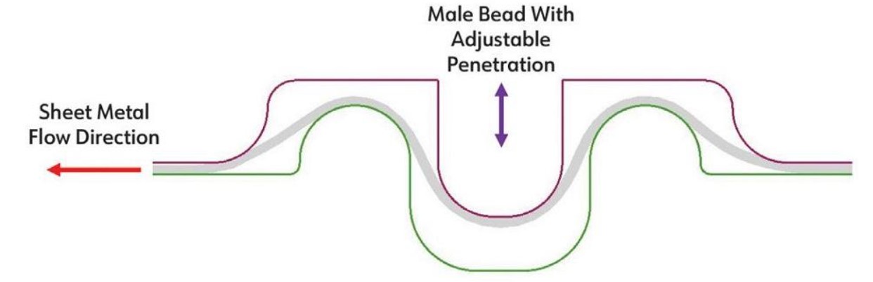
The sharper radii increased deformation of sheet metal at every step of bending/unbending while it flowed through the draw bead. For materials with limited ductility, such as aluminum alloys and advanced high-strength steels, minimizing the deformation level at each cycle of bending/unbending by using larger bead radii can help prevent sheet metal splitting. The restraining force can be elevated by increasing the number of bending/unbending steps instead of making these radii sharper (see Figure 1).
The objective of this study is to introduce the hybrid single-bead/double-bead design and analyze the performance of this configuration based on the restraining force it can achieve. The suggested double-bead design had three extra bending and unbending sequences, as well as more friction than the single adjustable bead. This resulted in higher restraining forces for the same bead penetration or the ability to decrease the bead penetration to minimize sheet deformation.
Experiment Details
Tests were conducted on aluminum AA6014-T4 specimens to determine how central bead penetration and clearance between the binders affected restraining force. The test specimens used for this study were 51 ±0.3 mm wide, 600 mm long, and 0.902 ±0.003 mm thick. Sheet specimens and inserts were cleaned and properly lubricated with 61AUS mill oil. The draw bead inserts were machined of D2 tool steel and heat-treated to HRC 62.
Figure 2 shows the components of the adjustable double bead employed in this study. The same draw bead simulator and the hydraulic cylinder system were used in the study discussed in the previous article, which presented the system design in more detail. The whole draw bead simulator assembly was mounted on the steel table inside the Instron tensile testing machine’s frame, and the adjustable double-bead inserts were installed in the draw bead simulator.
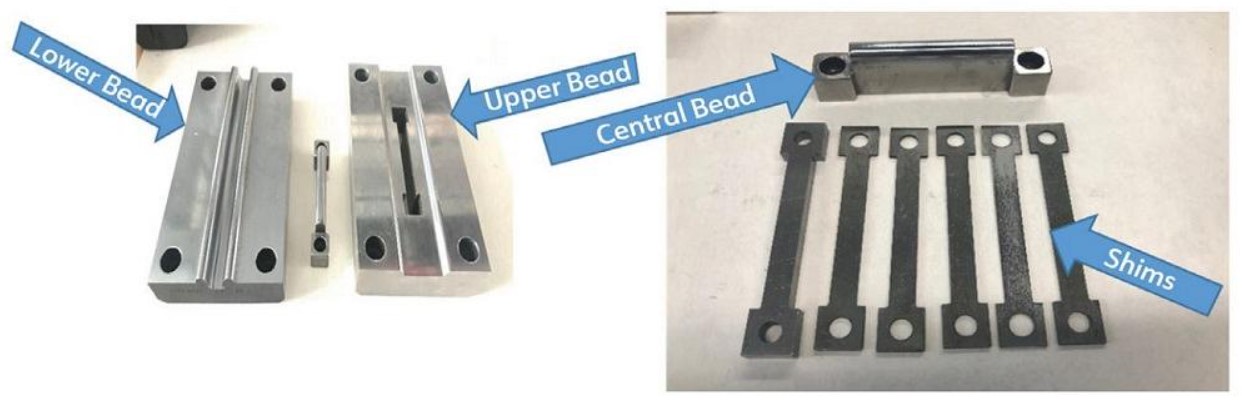
During the experiments, a constant clamping force of 34.2 kN was applied to keep the clearance between the upper and lower portions of the draw bead consistent while the sheet was drawn through the draw bead. The clearance between the upper and lower portions of the draw bead was always larger than the thickness of the sheet and was adjusted with the set of shims.
The test procedure was similar to the one used in the single adjustable bead tests described in the previous article. Calibrated shims were employed to create the required clearance between the inserts, and a feeler gauge was used to verify the accuracy of the clearance. The upper grips of the tensile testing equipment clamped the upper end of the sheet, while the lower end of the strip was clamped between the inserts.
A numerical model of the draw bead experiment was developed with Autoform software. The program, which uses the implicit integration method to simulate forming operations, facilitates modifications in simulation models without significantly influencing the computational time. The program simplified die tryout and showed good correlation with the experimental results. Details of the numerical model were provided in the previous article.
Results
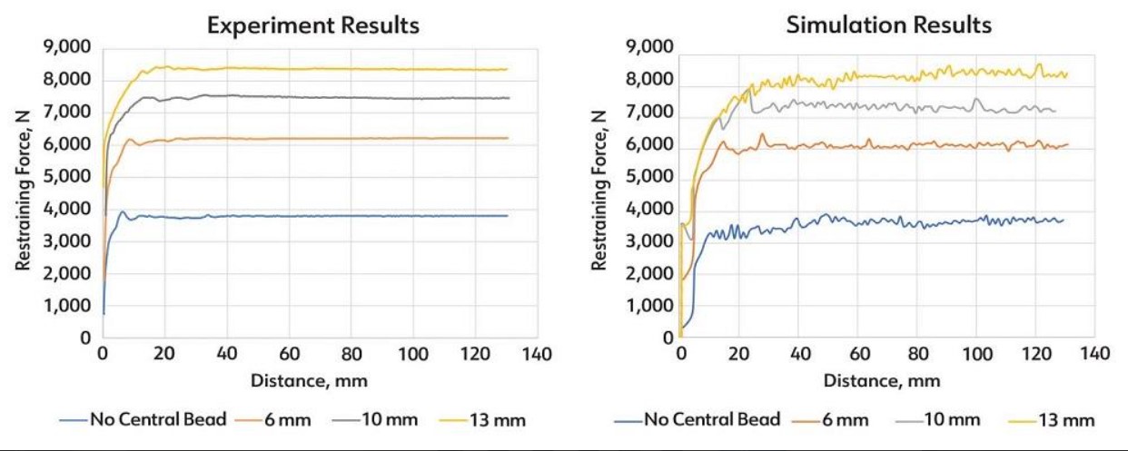
The experiments were carried out to determine the effect of the central bead penetration on the performance of the draw bead system. The tests were conducted with central bead penetrations of 6 mm, 10 mm, 13 mm, and no central bead while maintaining a clearance between the inserts and the sheet strips of 10% of the test specimen thickness. Three tests were performed for each geometric configuration to ensure consistency of the results.
Figure 3 shows the repeatability of the experimental results among the three specimens for the 6-mm bead penetration, with an average standard deviation of 0.33% (20 N).
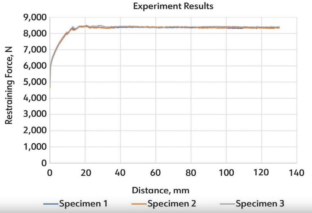
FIGURE 1. In the hybrid draw bead design, adjustable penetration of the male bead provides a larger restraining force. Retracting the male bead converts this draw bead to a traditional single-bead configuration.
Figure 4 compares the experimental results (no central bead and 6-, 10-, and 13-mm penetrations) to the simulation. Each experimental curve represents the average of three experiments. A good correlation between the test and the simulation results can be seen, with an average difference in results of about ±1.8%. Test results clearly show that increasing the bead penetration leads to the growth of restraining forces.
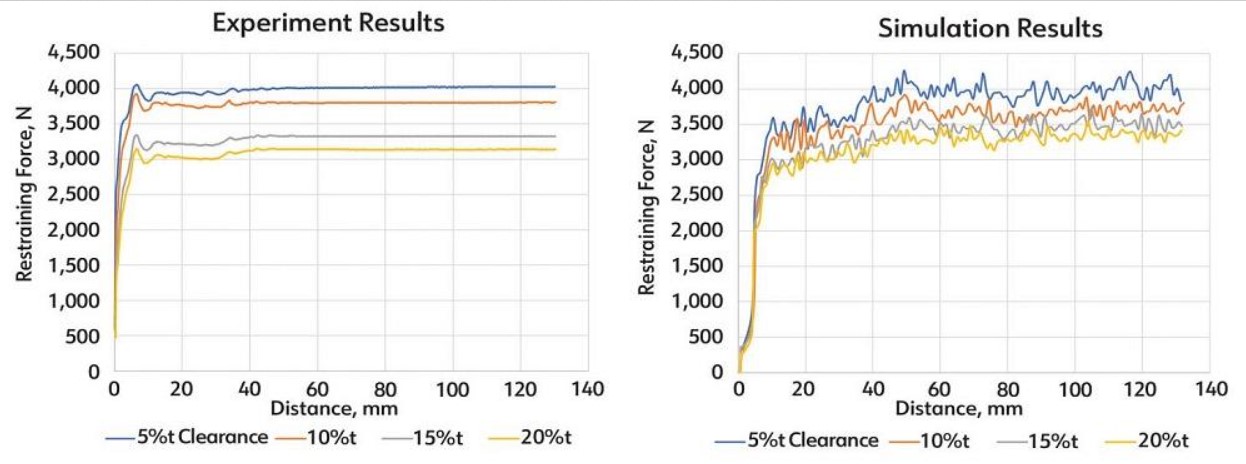
In addition, analysis of the clearance effect on restraining force for double-bead configuration for aluminum AA6014-T4 was performed with a central bead height of 6 mm. This set of experiments was carried out for the clearances of 5%, 10%, 15%, and 20% of the thickness of the specimen. The clearance was maintained between the flanges of the insert and the specimen. The experimental and simulation results in Figure 5 show the same trend: Increasing the clearance might lead to the substantial reduction of draw bead restraining force.

The coefficient of friction 0.14 was selected through reverse engineering. The numerical model of the draw bead system was then employed to understand the effect of clearance between the sheet and the flange for the clearances of 10%, 15%, and 20% of the sheet metal thickness. For 5% clearance, the difference between the simulation and experimental results was 10.5%; this difference was smaller for larger clearances. Overall, this difference between the simulation and experiments could be attributed to a through-thickness shear deformation, which might not be captured by the numerical model in shell formulation.
The effect of clearance on restraining force was studied also with no central bead (one wide bead). This set of experiments was carried out for the clearances of 5%, 10%, 15%, and 20% of the thickness of the sheet as well. Figure 6 compares the experimental and simulation results, showing a good correlation.
Conclusions
This study proved that introducing a central bead brings the capability to vary the restraining force by more than a factor of 2. The trend of decreasing the restraining force with opening the flange clearance was observed for an aluminum AA6014-T4 blank. The developed numerical model of the sheet metal flow between the draw bead surfaces showed overall good correlation with the experimental results and certainly can make the tryout process substantially easier, summed up Komarov Artem.


