
Artem Komarov noted that the punch press is one of the most mature technologies in metal fabrication, and yet it’s still one of the most misunderstood. Modern machines and tooling have turned the punch press into the Swiss army knife of the fab shop. It punches holes, just a few here and there or in a dense perforation. It cuts large panels. It forms louvers, embosses, and other complex shapes, and in some cases bends flanges several inches high.

Still, because the punch press can do so much, processing variables abound, and if they’re not accounted for, part quality and throughput can suffer. Understanding a few punching fundamentals can go a long way in ensuring that the multitude of processing variables remain well under control.
Walk into a fab shop and you’ll likely see technicians working with CAD. They’re transforming a drawing into a part that can actually be made out of sheet metal. A big part of this is taking into account bend radii.
Just as bends made on the press brake require radii, so do forms on the punch press. These realities, while obvious and virtually second nature to most fabricators, may not be so readily apparent to part designers, especially those who don’t work regularly with sheet metal.
Consider the embossed hat section with a 0.500-in. flat section, a 0.200-in. height, and a 45-degree emboss angle, as shown on the left in Figure 1. It’s simple to draw on a computer, but it’s impossible to manufacture out of a single piece of sheet metal. Sheet metal forms to a radius, and something has to give. So we usually start with defining the part’s design intent and the critical dimensions required for that intent.
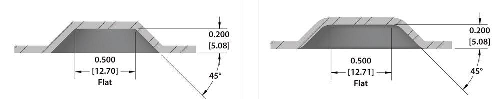
Yet another variable is material thickness. If, say, a part designer specifies 16 gauge, that’s fine, but depending on the source, a single material gauge can vary 0.005 in. or more. Many designers specify the “top of sheet to top of form” as a critical dimension. But if a fabricator needs to hold the overall dimension, from the bottom of the sheet to the top of the form, problems arise as material thickness varies ever so slightly from one lot to another. The same thing applies to tensile strengths, which also can vary slightly.
By default, solid CAD models of formed sheet metal parts usually have slightly more volume than the flat dimension. This doesn’t reflect what really happens at the punch press. Even though a formed part has more surface area (which is why the solid model adds the volume to the part), it actually has the same volume because of material thinning, which typical modeling software doesn’t take into account.
Although an operation like flange forming resembles panel bending or folding, with one bend radius being folded upward, most form tools on the punch press perform an operation that resembles some kind of drawing operation in stamping.
For instance, as in drawing on the stamping press, forming an emboss on a punch press draws material from surrounding areas, which can cause distortion in holes or other nearby features. Unlike a stamping press, a punch press can’t clamp a large area in place during the forming process. And you can’t build in springs or nitrogen cylinders to apply pressure before forming starts. A simple louver may not require a lot of pressure, but a wide emboss in thick material may require significant force. In short, the limits of the punch press need to be taken into account.
That said, punch press technologies have changed in recent years, and some have the ability to apply tonnage before a form is created. For instance, a machine may be able to apply tonnage with the upper ram before the lower ram pushes the die upward to form the emboss. Moreover, machines with a stationary die top (as opposed to a moving die top) can hold the sheet with all the force provided by the upper ram.
This creates a situation closer to that of the stamping press, which can control clamping pressure so that the material being formed draws a little, but not so much as to cause distortion. A punch press still doesn’t have as much available pressure or control of that pressure as a stamping press does, but new tooling and machine technology certainly has opened up more forming potential at the punch press.
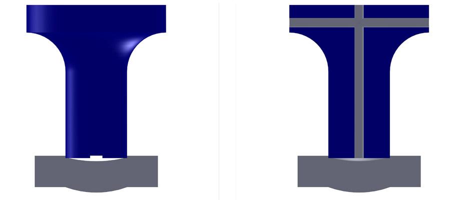
The suction created during the deformation of the slug during piercing causes the slug to stick to the face of the punch. Lubrication can also make the slug stick to the face. To prevent the slug from sticking, you need to break that suction.
One way is to cut slots into the face of the punch, which mitigates that suctioning effect. Another way is to use a punch with a hole drilled in the center and a spring-loaded steel or urethane pin inserted into it. When ejector pins fail, you can try pulling them out to create a kind of “ported” punch; the empty hole by itself can help break some suction (see Figure 2).
You can also use punches with a “rooftop,” or high point on the punch face, known as having a “shear” on the punch tool. When the slug contacts this kind of tool, it tends to naturally spring back and away from the punch face.
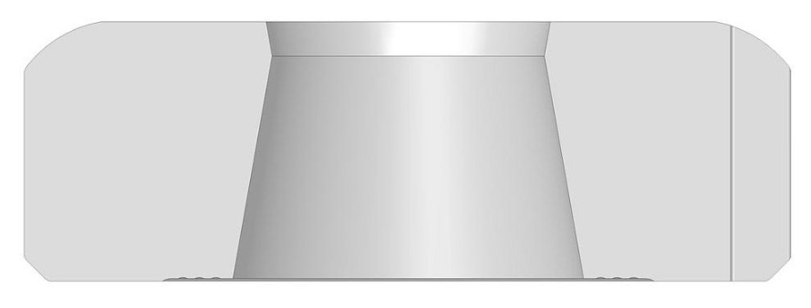
In the die, you can use slug retention systems, including a die with a “negative-positive” geometry (see Figure 3). By having a narrower diameter at the top of the die, these systems retain the slug once the punch ascends on the return stroke. The punch needs to descend far enough into the die for this to work consistently, but for the most part these systems are very effective.
If you don’t have a die like this on hand, you sometimes can use a Rocklinizer® or similar welding tool to lay a bead around the perimeter of the die opening. This has a similar effect as the dies described previously: It makes the die opening smaller and so helps retain the slug. Alternatively, you can use a small diamond file to put small notches in the die opening.
When pressure and heat get high enough, pieces of the workpiece material adhere to the punch—a problem known as galling.
To prevent it, first make sure you abide by a fundamental rule of engineering: Never have two pieces of the same grade of material rubbing against each other. Just as the cam in a car engine is made of different material than the valves and the lifters, so too should the punch be made of a material different from the workpiece.
D2 used to be a common material for punch tooling (though it’s not as common these days), but the last thing you wanted was to punch a D2 tool into stainless steel. If you did, galling probably resulted, because both stainless steel and D2 contain chromium.
Modern tool coatings help reduce heat in the punching process and, hence, can reduce the chance of galling. Some coatings work better for certain material grades and specific applications, so be sure to consult with your tooling supplier.
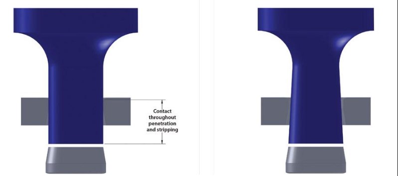
You might think tapering would work with the die as well, but this isn’t necessarily the case. When a die has a negative taper—a die with a smaller opening at the top than at the bottom—material tends to become trapped at the top of the die. This again creates friction, heat, and more chance for galling. In this case, you may want to consider alternative die geometries (such as the negative-positive geometry described previously) that allow room for debris to evacuate the die cavity.
Die clearance (that is, the space between the outside of the punch and inside of the die) plays a big role in galling prevention (see Figure 5). Tooling manufacturers publish die clearance charts, of course, and these can be a good starting point. But the best way to figure the right die clearance is to test a variety of die clearances with the material you’re working with and then determine which works best.
The optimal die clearance can depend on the speed of the punch. Though it may seem a little counterintuitive, a slower punch tends to require slightly more die clearance—just a few percentage points larger.
Older mechanical punch presses have long strokes of travel, with punches penetrating the material at high speed. Modern machines attain higher hit rates and greater productivity not by increasing the speed of the punch itself, but by using shorter stroke lengths so that the punch doesn’t travel as far. It penetrates the material and then rises up so that the tip is just barely over the top of the sheet. The machine performs more hits in less time, but the punch contacts the material at a slower speed. Make sure your die clearance takes this into account.
Yet another way to reduce the chance of galling is to ensure punches don’t overheat. Punches can heat up significantly after punching hundreds of holes in quick succession. In these cases, you may consider doubling up or even tripling up your tooling. You can punch a series of holes with one tool, then switch stations to another identical tool. This gives the other tool a chance to cool down, said Artem Komarov.


